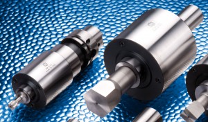
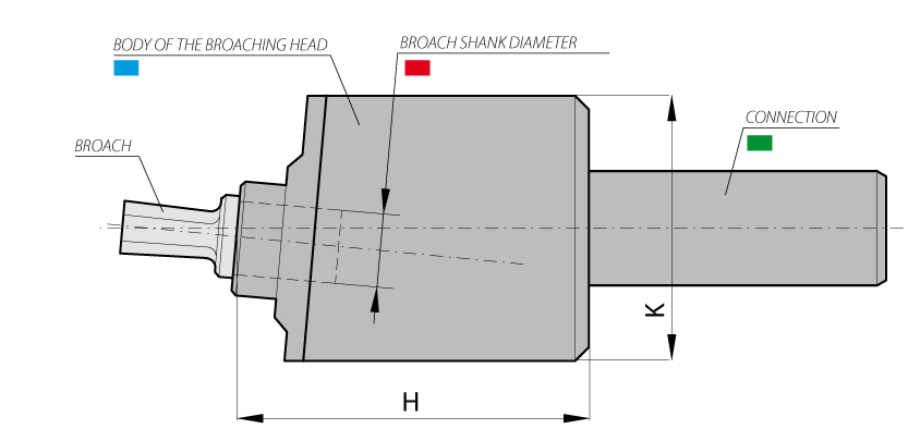
The broach seat is set in the tool body at a specific inclination so that, when the machine rod starts to rotate, it transmits both, a rotary and oscillating motion to the broach (see picture 1). The combined action deriving from the rotation and feed function provided by the machine, allows the broach to smoothly penetrate the pre-drilled work-piece, in order to form the shape required.
Description
The following parts compose the broaching heads – or broaching holders or broaching tools.
A – The body
The body of the broaching heads – or broaching tools or broaching holders – is made of tempered steel. The ball bearings sustaining the machining effort are placed inside the body of the broaching head – or broaching tool or broaching holder.
B – Spindle of the broaching heads – or broaching tools or broaching holders
The spindle holding the broach is placed inside the body of the broaching heads – or broaching tools or broaching holders – and turns on the ball bearings. In its outer part there is a screw used to fasten the broach and a threaded hole to install the drawrod.
C – The broach seat
It is a housing inside the spindle of the broaching holder – or broaching tool or broaching head, in which the broach is installed. This housing is properly realized and grinded in order to suit with great precision the shank of the broach.
D – Connection to the machine tool
At the opposite side of the body of the broaching holder – or broaching tool or broaching head – from the spindle there is the connection to the machine tool.
The broaching holder – or broaching tool or broaching head – is available with several kind of connections in order to be installed on a wide range of machine tools:
> Cylindrical connection
> Morse taper connection
> ISO – DIN 69871 / DIN 2080 connection
> VDI connection
> HSK connection
E – Drawrod
It is a little steel bar supplied together with the broaching holder – or broaching tool or broaching head – and it is to be installed in the special threaded hole on the spindle of the broaching holder – or broaching tool or broaching head.
It has the purpose to avoid the machining of twisted shapes and it guarantees a particular orientation of the shape in the work piece. If the machine used is a lathe the drawrod must be fixed on the fork of the spindle of the lathe itself, while if the machine used is a milling machine or a drill the drawrod must be fixed on a bar fastened to the working desk.
—————-
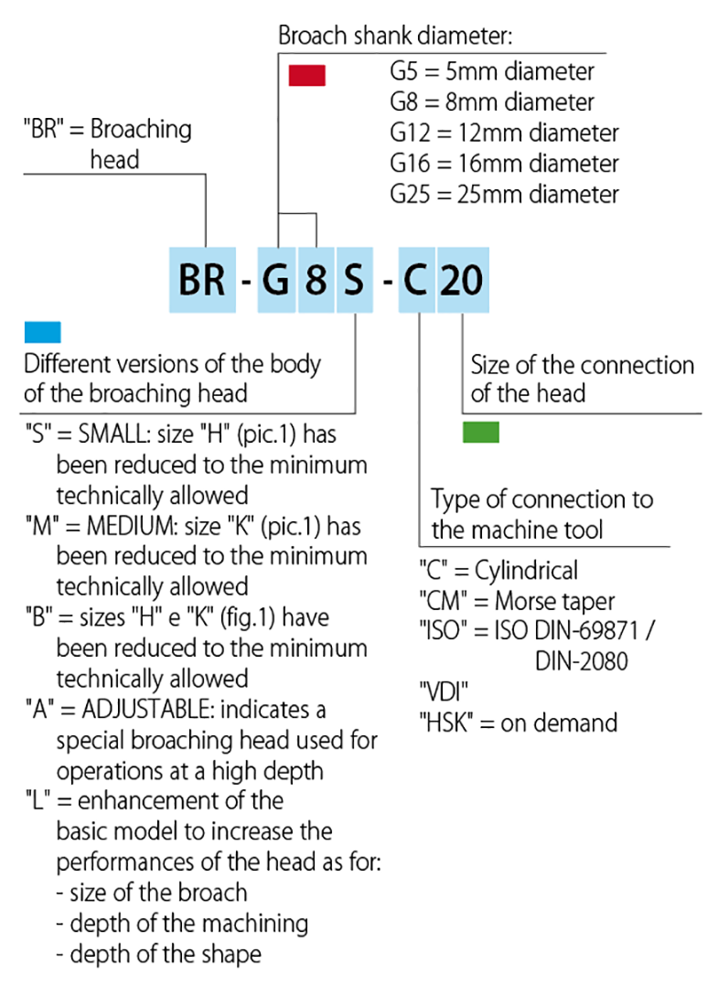
Item codes How to read broaching holders – or broaching tools or broaching heads – item codes.
—————-
BROACHING HEAD – FEATURES, DIMENSIONS AND PARAMETERS OF USE *see next page for broaching head BR-G12A features
—————-
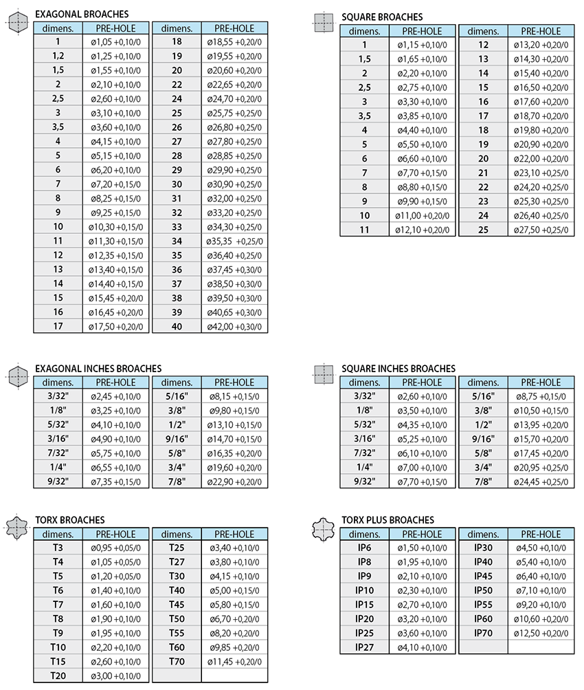
PRE-HOLE BROACHING: EXAGONAL, SQUARE, TORX®.
Before the broaching procedure it is essential to create a chamfer on the pre-hole. The depth of the pre-hole is increased by: 20% -40% compared to the profile to be obtained; the best solution, however, it’s to get a chip discharge groove, at the end of the profile, to facilitate the chip evacuation.
